EN
EN English
 中文简体
中文简体 Français
Industry News
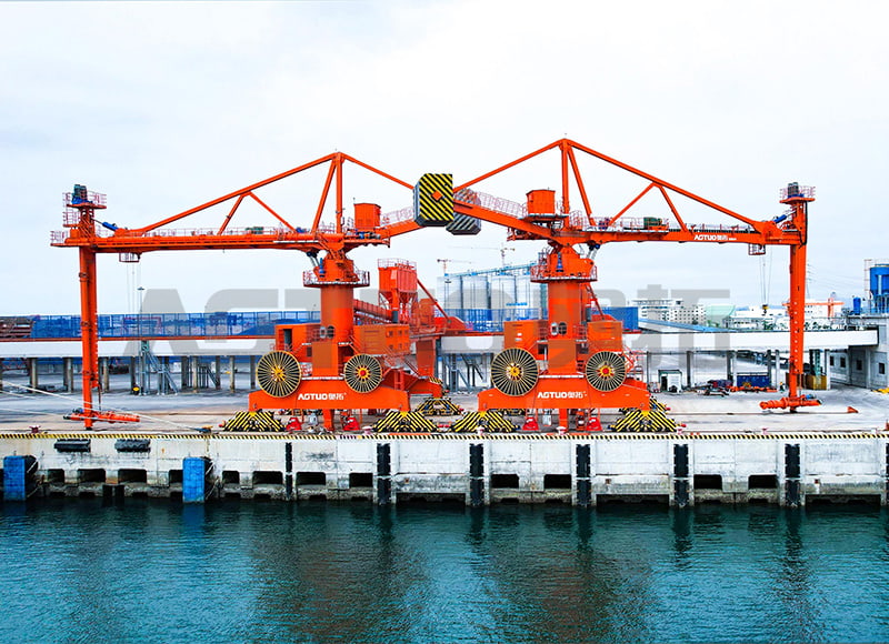
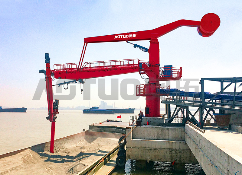
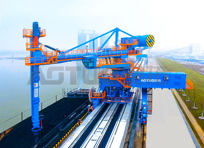
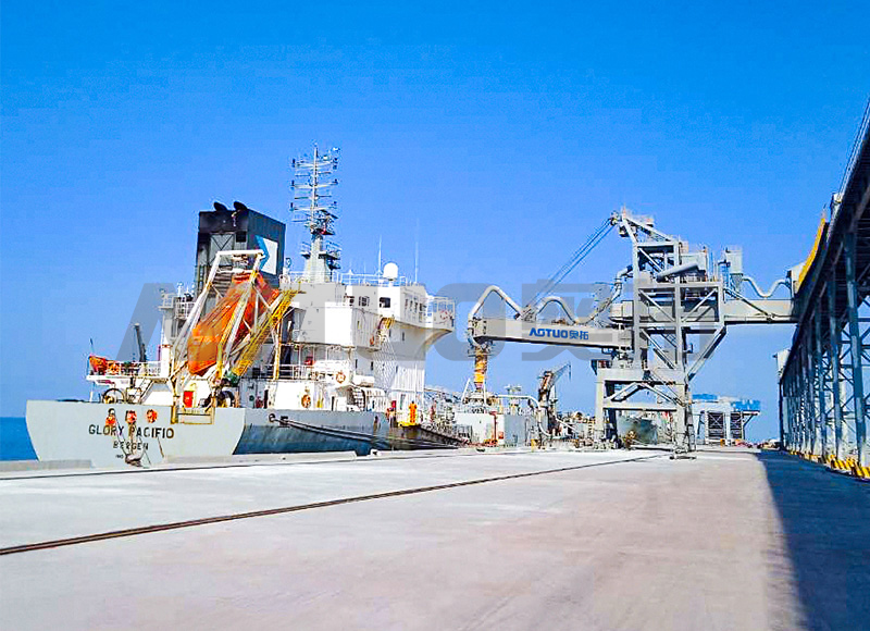
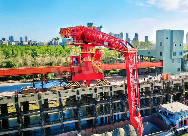
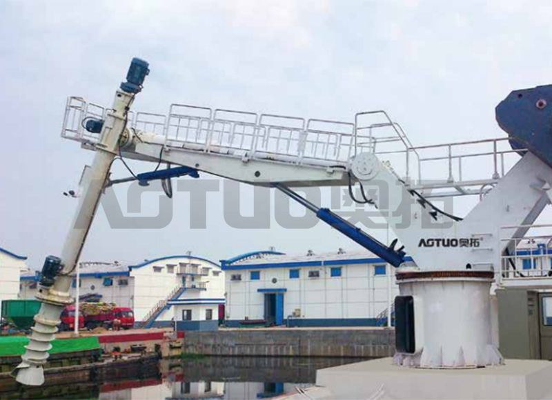
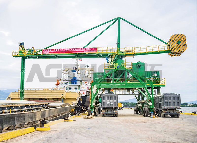
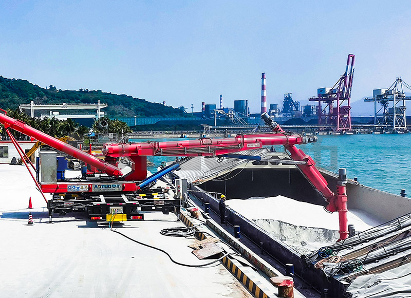
Home / News / Industry News / How to Choose a Mobile Ship Loader: Capacity, Material Handling, and Operational Efficiency

It is focused on the overall solution of dry bulk material port transfer system,
research and development, manufacturing, and service
Copyright © Hangzhou Aotuo Mechanical and Electrical Co., Ltd. All Rights Reserved.
Custom Material Conveyor Transfer Systems Manufacturers