EN
EN English
 中文简体
中文简体 Français
Industry News
Home / News / Industry News / Bulk Ship Loader Boom: Key Structural & Operating Requirements Explained

Article Directory
A 180,000 DWT bulk carrier measures roughly 45 meters across the beam. To place cement, coal, or grain into every corner of its hatches, a bulk ship loader boom must reach past the vessel's centerline, luff down as the cargo level rises, and slew to align with each hatch opening. Get the structural and operating requirements wrong, and the result is more than slower loading: it is cracked hull plating, segregated cargo, and weeks of unplanned repairs. This article explains what a loader boom must do, how it is engineered, and which operating limits keep it safe, drawing on systems built by Hangzhou Aotuo Mechanical and Electrical Co., Ltd. (AOTUO) over more than 20 years of port equipment manufacturing.
The boom is the load-bearing arm that transfers bulk material from the dock conveyor to the vessel hold, and every critical performance limit of a loader, from reach and throughput to dust control and safety, is governed by its design.
A bulk ship loader boom is a luffing, slewing, and usually telescoping structural arm that carries a belt conveyor and a discharge spout from the loading machine to the ship's hatch.
In continuous loading operation, the boom performs four functions at the same time:
The boom structure must resist continuous fatigue loading, wind loads, and the dynamic forces of a moving belt while keeping deflection within limits that protect both the machine and the vessel.
The boom conveyor carries material from the feed point to the discharge end and is the main structural part of the loader. The belt, idlers, and drive pulley are mounted directly on the boom frame, so the structure carries both dead weight and dynamic belt tension in every cycle.
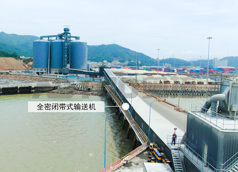 Belt Conveyor for Loose and Finished Bulk MaterialsThis conveyor handles powders, granules, and small blocks with capacities from 10 to 3000 t/h and belt widths up to 2200 mm, making it a versatile component for boom-mounted transfer systems in marine terminals.View Product →
Marine-terminal booms are typically fabricated from high-strength structural steel with a corrosion protection system rated for salt-laden air. Welded box-girder sections provide high torsional rigidity at lower mass than open lattice frames, which directly reduces the overturning moment on the slewing ring and the supporting gantry.
The telescopic section rides on replaceable wear pads and is driven by racks or hydraulic cylinders. Luffing cylinders must raise the boom with a fully loaded belt and hold it steady against wind gust loads. The combination of luffing angle, telescopic stroke, and slew arc defines the machine's working envelope.
| Parameter | Typical range | Design impact |
| Boom reach | 20-45 m | Set by the beam of the largest vessel served |
| Slew arc | 90-180 degrees each way | Determines berth coverage and hatch access |
| Luffing range | -10 to +20 degrees | Controls drop height as the hold fills |
| Telescopic stroke | 3-8 m | Reduces machine travel for hatch-to-hatch moves |
| Belt speed | 2-4 m/s | Balances throughput against dust and belt wear |
| Fatigue life | 20-30 years | Governs weld details and inspection intervals |
Operating requirements govern how the boom moves during a loading cycle: positioning accuracy, motion speeds, interlocking, and dust suppression together decide whether a terminal reaches its designed throughput.
Boom luffing typically operates at 1-3 m per minute measured at the spout tip, slewing runs at 5-15 m per minute, and traveling at 10-30 m per minute. In automatic mode, positioning accuracy is usually within 100 mm at the spout, which is necessary for hatch guarding and for trimming systems that distribute cargo evenly across the hold.
Dust is controlled at the boom by keeping the drop height as low as possible and by using a telescopic spout with an inner cone that lets air escape without carrying dust outward. For grain, drop height also affects breakage rates, while for cement and clinker, moisture and fines generation are the dominant concerns.
Maintains a short, controlled drop distance as the hold fills and retracts to clear hatch coamings during travel.
Simple and inexpensive but requires the boom to be luffed repeatedly to manage drop height and dust.
Boom configuration must be selected from the vessel fleet, berth layout, and annual throughput target, not from a generic specification.
For a terminal serving Handysize to Supramax vessels in the 30,000-60,000 DWT range, a 20-25 m boom reach is usually enough. A Capesize berth at 180,000 DWT calls for 35-45 m of reach, heavier structural sections, and a more powerful luffing system. Rail-mounted loaders such as the AOTUO rail mobile ship loader travel along the berth and use the boom's slew and telescope to trim individual hatches, which cuts repositioning time and keeps the boom shorter than a fixed-loader equivalent.
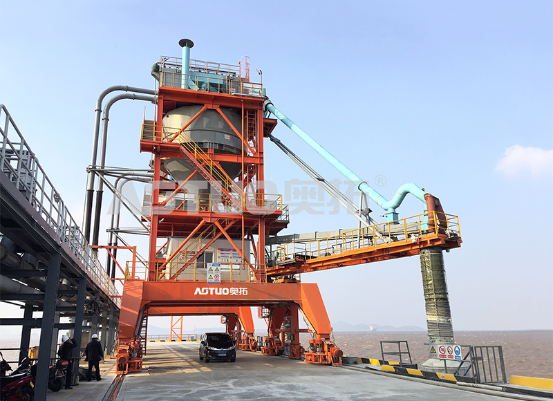 Rail Mobile Ship Loader for Bulk Materials (300-1500 t/h)Designed for vessels from 800 to 50,000 DWT, this loader offers 20-25 m boom reach for Handysize to Supramax ships, with low energy use and dust control, ideal for efficient berth-side loading operations.View Product →
The same trade-off between rail travel and boom reach is visible in operation at AOTUO's Brisbane port project, where a travelling loader covers multiple hatch positions without requiring an oversized boom to span the full vessel.
Planned inspection of the boom structure, welds, and moving interfaces is the only reliable way to prevent fatigue failures that can shut down a terminal for weeks.
Typical boom reach ranges from 20 m for terminals serving Handysize vessels to 45 m or more for Capesize berths; the correct figure is determined by the beam of the largest vessel in the port's fleet.
Telescoping reduces the distance the whole machine must travel, allows precise spout positioning, and keeps the drop height low throughout the loading cycle, which cuts dust and cargo breakage.
Visual checks of welds and structural members run continuously, with phased-array ultrasonic testing of critical joints on a 12-month cycle; terminals in corrosive marine environments often move to six-month intervals.
High-strength structural steel with welded box-girder or lattice sections, protected by marine-grade coating systems; wear surfaces at the telescope section use replaceable polymer or bronze pads.
It is focused on the overall solution of dry bulk material port transfer system,
research and development, manufacturing, and service
Copyright © Hangzhou Aotuo Mechanical and Electrical Co., Ltd. All Rights Reserved.
Custom Material Conveyor Transfer Systems Manufacturers