EN
 English
 中文简体
 Français

Industry News
Home / News / Industry News / Travelling Ship Loader Rail System: Key Structural and Alignment Factors

Article Directory
A 50,000 DWT bulk carrier sits alongside the berth with hatches spread over nearly 190 metres of quay. The travelling ship loader must traverse that full length, slew, luff, and extend its boom to lower the loading spout into every hatch opening. A travelling ship loader rail system is the track-and-undercarriage assembly that carries the machine's full weight, guides it along the berth, and holds the spout aligned to the vessel's hatch line. When the rails are straight, level, and true to gauge, the loader performs at rated capacity. When alignment drifts, the wheel flanges, bogie frames, slew bearing, and boom cylinders all begin to pay the price.
The rail system determines how much of a travelling ship loader's nameplate capacity can actually be used at the berth. Rated capacity is achievable only when the gantry stays stable and the spout holds position over the hatch: the rail gauge defines the stability envelope against wind and ship-contact loads, and foundation stiffness controls settlement that would lift one wheel clear of its rail.
At a large bulk terminal, a loader often travels 200 m or more to serve every hatch of a Panamax or Capesize vessel. That travel distance multiplies the effect of even small alignment errors: a 2 mm lateral deviation becomes a repetitive impact load every time the machine passes over it, which can mean tens of thousands of loading cycles each year.
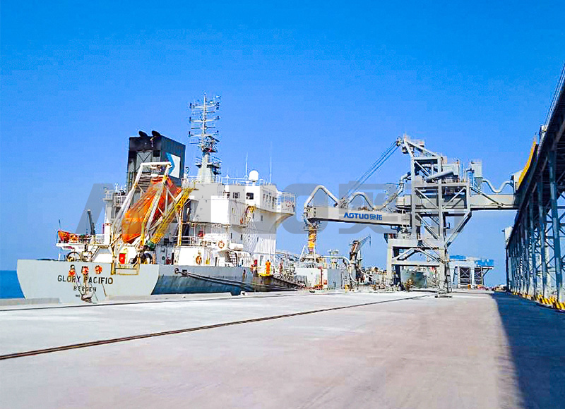
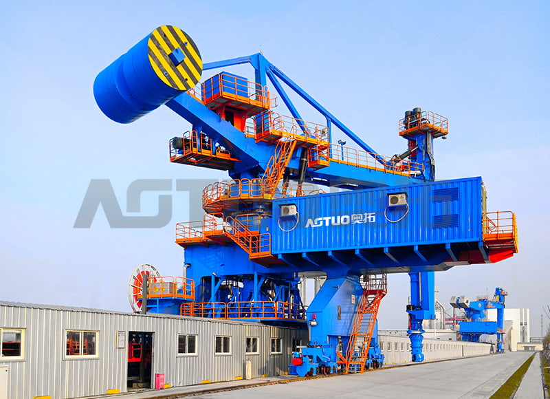
The same rail performance logic shows up at Huizhou Port in Guangdong, where rail-mounted equipment from Hangzhou AOTUO Mechanical and Electrical Co., Ltd. (AOTUO) operates on a berth that handles multiple vessel classes. The port relies on the rail system to keep spout positioning accurate across the full travel length, because a loader that cannot hold alignment costs berth time on every call.
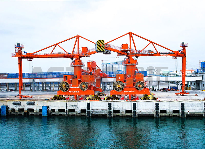
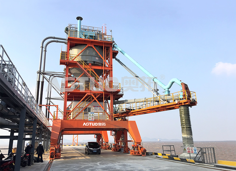 Rail Mobile Ship Loader for Bulk Materials, 300-1500 t/h, 800-50000 DWTThis rail-mounted loader is the unit operating at Huizhou Port, designed for bulk cargo loading across multiple vessel classes. Its capacity and energy figures are relevant to the alignment and berth-time concerns discussed in the surrounding text.View Product →
A travelling ship loader rail system is built from five load-bearing layers: the pile foundation, the support beams, the rail fasteners, the rail section, and the gantry wheel assemblies. Each layer has a distinct failure mode that terminal engineers must inspect on a schedule.
| Layer | Primary function | Common field failure |
| Pile foundation | Transfers gantry wheel loads to competent soil | Differential settlement after heavy typhoon loading |
| Support beam | Distributes wheel loads along the rail base | Fatigue cracking at pile cap interfaces |
| Rail fastener | Holds the rail in position while allowing thermal movement | Loosening and corrosion in marine salt air |
| Rail section | Provides running surface and lateral guidance for wheels | Side cutting and head wear from flange contact |
| Gantry wheel assembly | Carries vertical load and drives travel motion | Flange wear and bearing overheating |
Rail gauge is the clear distance between the inner faces of the two rails on which the gantry travels. It is fixed at design stage and must remain the same along the entire travel length, because the gantry wheels are laterally constrained by the rail heads.
The same structural logic appears on the unloading side of the process. AOTUO's rail-mobile screw ship unloader carries its vertical screw assembly over the same gantry-and-rail architecture, with identical requirements for foundation stiffness and alignment control.
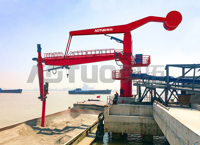
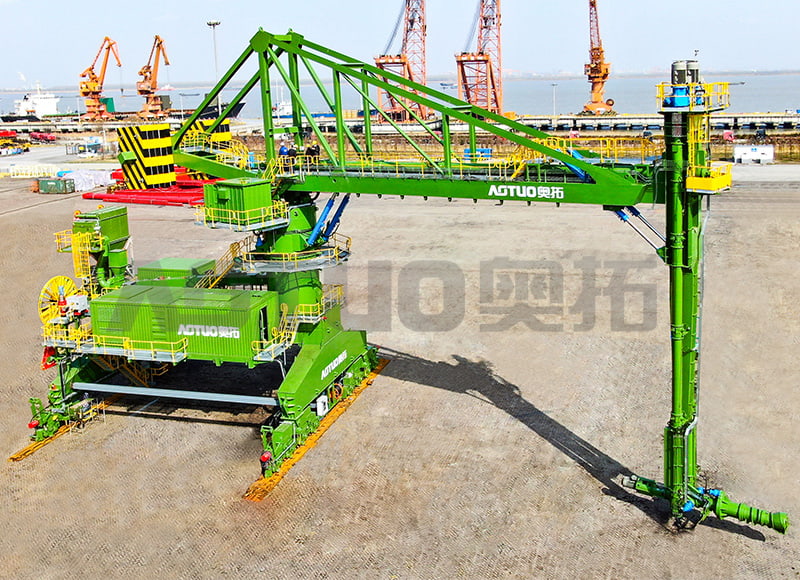 Rail Mobile Screw Ship Unloader for 1000-70000 DWT VesselsThis unloader shares the gantry-and-rail architecture described in the adjacent paragraphs, with a spiral mechanism that tracks material in three dimensions. It is positioned as the unloading counterpart to the loader, important for evaluating the same rail system.View Product →
Rail alignment for a travelling ship loader is defined by three measurable parameters: gauge, vertical level, and longitudinal straightness. These values are set at installation and verified against a baseline survey that the terminal records for future comparison.
Wheel contact stays on the central tread, flange wear stays uniform, and the slew bearing sees balanced loads. The loader holds spout position within the hatch, which reduces spillage and trimming time.
Wheel flanges contact the rail head side, the gantry yaws as it travels, and the loading spout oscillates relative to the hatch centre. Spillage increases, and structural fatigue accelerates at every joint.
Figure 1. Gantry wheel flange wear increase versus lateral rail misalignment
The wear curve is not linear. Between 3 mm and 5 mm of lateral misalignment, the rate of wheel flange and rail head deterioration increases sharply, which is why leading terminals set their intervention threshold at 4 mm rather than waiting for visible damage.
The contact area between a gantry wheel and the rail head is a small ellipse, typically 10-20 mm across. Every millimetre of misalignment shifts that contact point and changes the load path through the bogie frame into the main gantry structure.
A travelling ship loader wheel tread is machined with a slight taper, typically 1:20 conicity, which keeps the gantry self-centred on the rails. If the rail gauge opens or closes, the contact point moves toward the flange root, and the self-centring action weakens.
When one rail settles lower than the other, the diagonal bogie on the higher rail carries a larger share of the dead load and the live load from the material stream. That overload shows up first as bearing temperature rise on the affected wheel, then as spalling on the rail head under the wheel.
Wheel conicity is the taper ground into the gantry wheel tread that produces a smaller rolling radius on one side of the wheel pair, steering the gantry back to the rail centreline.
Alignment accuracy is set during installation and preserved by the foundation. Re-aligning a travelling ship loader rail after commissioning is expensive and disrupts berth operations, so the sequence must be executed correctly the first time.
Terminals that compress the final grouting step to reduce berth downtime often see alignment drift in the first year. The grout bed should cure fully before the loader is allowed to travel at rated speed.
A rail system that passes installation tolerances will still drift over time. Foundation settlement, thermal cycling, fastener corrosion, and accidental overload from ship impact all contribute to progressive misalignment that must be caught by a scheduled survey program.
Coal terminals running AOTUO's rail-mobile screw coal ship unloader follow the same annual survey discipline, with additional attention to rail head condition because coal dust accelerates abrasive wear. The automation interface between the travel drive and the berth management system also depends on accurate position feedback along the rail path, as covered in AOTUO's analysis of automation technology for rail-mobile ship loaders.
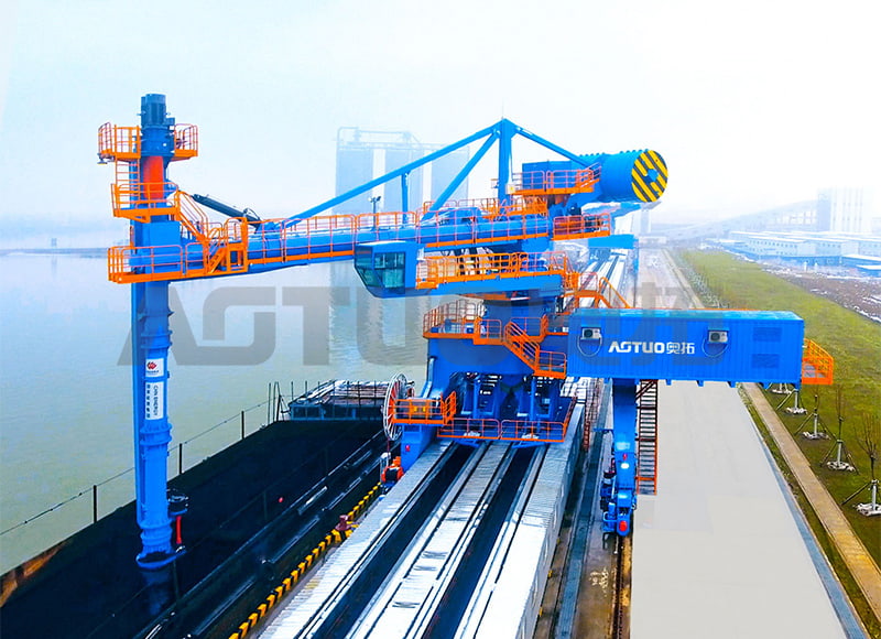
 Rail Mobile Screw Coal Ship Unloader, 200-3000 t/h, Up to 200000 DWTBuilt for coal terminals, this unloader highlights the abrasive wear and automation feedback issues raised in the paragraph before the card. It is a large-capacity option relevant to terminals managing heavy-duty rail operations and annual survey requirements.View Product →
The commonly specified gauge tolerance is +/-3 mm from the nominal dimension, measured between the gauge faces of the two rails at any cross-section. Relative elevation between the rails at the same cross-section should stay within +/-3 mm, and the vertical level of each rail within +/-2 mm over any 2 m span.
At minimum, a full laser survey once per year, quarterly simplified measurements of key cross-sections, and a monthly visual inspection of fasteners, rail heads, and the travel channel. Surveys should also be run immediately after typhoon events or any vessel contact with the loader.
The dominant causes are differential foundation settlement, loosening of rail fasteners under cyclic loading, thermal expansion where expansion joints were poorly designed, and impact loads transmitted from the vessel through the loading spout. Rail misalignment is rarely caused by a single event; it accumulates over operating time.
The retrofit is technically possible, but the foundation, rail system, and gantry structure represent most of the cost of a new machine. In practice, terminals that need travel capability choose a new rail-mobile ship loader rather than converting fixed equipment, because the structural changes affect the entire machine base.
Alignment data from the quarterly survey should be recorded in millimetres with the survey date and the terminal's operating hours since the last survey. This creates the baseline needed to predict when intervention will be required.
It is focused on the overall solution of dry bulk material port transfer system,
research and development, manufacturing, and service
Copyright © Hangzhou Aotuo Mechanical and Electrical Co., Ltd. All Rights Reserved.
Custom Material Conveyor Transfer Systems Manufacturers